
Application / Custom wire assemblies
Motors & Drive SystemsWire Harnesses
Motor and drive-system wire assemblies connect motors, control boards and related components. Prepared wire leads can be supplied for direct soldering to a PCB, following your drawing or reference sample.
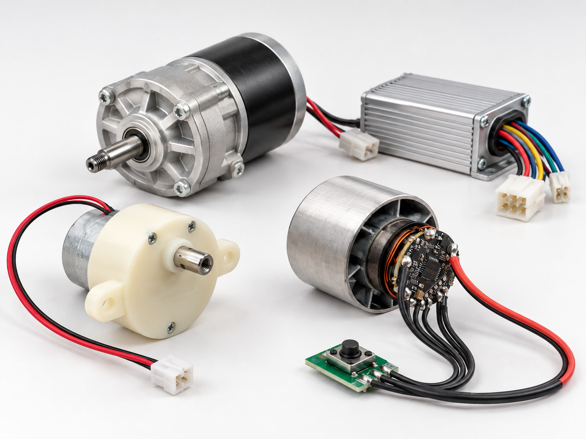
Application illustration. Depicted equipment and labels do not define supplied product specifications or customer projects.
01 / Connection points
What we connect
- Motor leads
- Control-board connections
- Local switches
- Sensor connections
- Related device components
- Prepared leads for direct PCB soldering
Installation context
Engineering considerations
Review these points against your actual equipment and agreed assembly drawing.
- Motor and controller connector orientation
- Lead routing and mechanical support
- Stripping and tinning requirements for PCB solder leads
- Customer-defined wiring, soldering and inspection criteria
Project handoff
What we need from you
Build-to-Drawing / Build-to-Sample
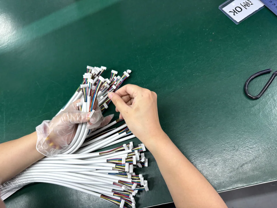
A BOM is not mandatory when the drawing or sample provides enough information. We can help identify connectors and organize the BOM.
- Drawing or reference sample
- Connector / terminal requirement
- Pinout / wire sequence
- Wire gauge: AWG + mm²
- Cable length / branch dimensions
- Quantity
- Testing / acceptance requirements
- Operating conditions and required material ratings
- Customer-specified materials, if applicable